A characteristic needs enough measured operating points to reveal its shape. Measuring one resistance does not establish proportionality.
By the end, you should be able to:
Collect signed I–V data safely.
Plot I against V with suitable axes.
Explain resistor, lamp and diode curve shapes.
Before you revise
Diagnostic question
Choose an answer from memory. Your result tells you what to watch for in the guide.
Core revision guide
Learn the model, then use it
A characteristic needs enough measured operating points to reveal its shape. Measuring one resistance does not establish proportionality.
01
Measure both polarities safely
Scope: 8463 and 8464 · Foundation and Higher
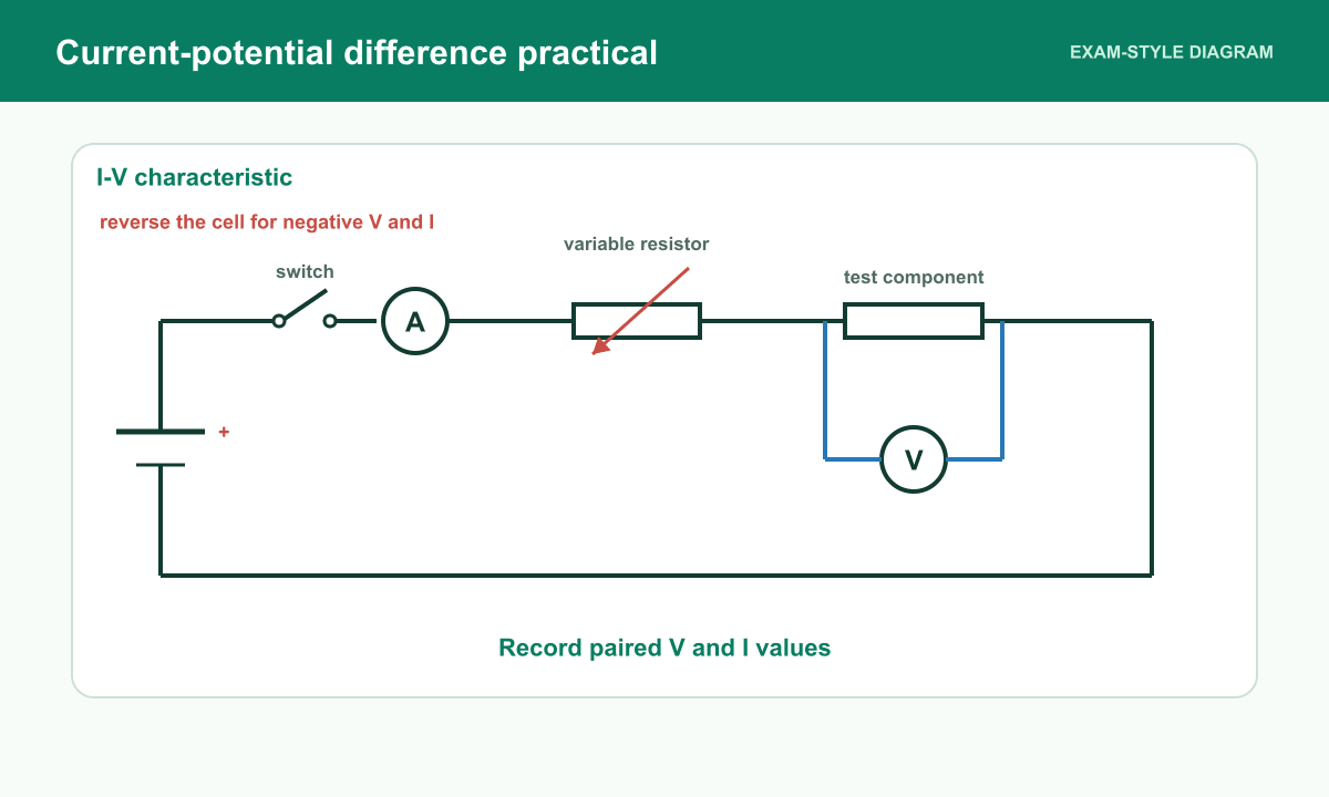
Use a low-voltage supply, switch, variable resistor and test component with ammeter in series and voltmeter across it. Include an appropriate limiting resistor when testing a diode. Start with high resistance, vary the supply/current gradually and record paired V and I. Reverse the supply connections with power off to obtain negative V and I; stay within ratings.
02
Plot I against V
Scope: 8463 and 8464 · Foundation and Higher
Label V horizontally and I vertically and show both signs. A resistor at near-constant temperature gives a straight line through the origin. A lamp is increasingly less steep as its hot filament resistance rises. A diode shows little reverse current and substantial forward current after its conducting region is reached; do not claim an exactly universal threshold voltage.
03
Temperature control depends on the component
Scope: 8463 and 8464 · Foundation and Higher
Limit heating for the fixed resistor so its curve measures the intended constant-temperature behaviour. Heating is part of the filament lamp’s normal characteristic: record stable readings at each point. Repeat readings to check scatter and use suitable meter ranges without exceeding the component’s safe power.
Vary the current safely, record paired V and I readings, then reverse the supply to obtain negative readings when required.Open the full-size exam diagram
Resistance at a pointR = V ÷ IΩ, V, A
Misconception clinic
Replace the tempting answer
Read each belief, say what is wrong with it, then compare your correction.
Tempting idea: R increases with voltage.
Use instead: V/I is 10 Ω at each point. This is proportionality under the measured conditions.
Tempting idea: To force equal reverse and forward currents.
Use instead: Directionality remains. A diode’s forward current can rise sharply.
Retrieval practice
Quick checks
Worked examples
See the method being built
Apply measure both polarities safely in the worked reasoning, then try the changed-context questions below.
Example 1 · Full I–V method
Scope: 8463 and 8464 · Foundation and Higher
Describe how to collect an I–V characteristic for a fixed resistor.
Use a variable d.c. supply, ammeter in series and voltmeter in parallel.
Take paired V and I readings in small steps.
Reverse the supply and repeat for negative p.d.
Show the answer
Plot current against potential difference. The fixed resistor should give a straight line through the origin if its temperature is constant.
Example 2 · Identify a graph
Scope: 8463 and 8464 · Foundation and Higher
An I–V graph has almost no current for negative p.d. and then rises sharply for positive p.d. Identify the component.
Look for one-way conduction.
Compare with resistor and lamp behaviour.
Name the component.
Show the answer
It is a diode, which conducts mainly in its forward direction.
Example 3 · Explain lamp curve
Scope: 8463 and 8464 · Foundation and Higher
Explain why the gradient of a filament lamp I–V graph falls at high p.d.
High p.d. gives higher current.
The filament temperature rises.
Resistance rises, so current increases less per volt.
Show the answer
The lamp gets hotter and its resistance increases, producing a curve rather than a straight line.
Exam precision
Use the physics precisely
Do this: Describe polarity reversal with the supply off, component protection and stable paired readings. Link each curve shape to its component behaviour.
Independent practice
Exam-style questions
Write an answer before opening the marking guidance. Then edit the exact phrase or step that would gain the next mark.
1. Describe how to obtain the positive and negative portions of a component’s I–V graph.
[4 marks]
Scope: 8463 and 8464 · Foundation and Higher
Show marking guidance and model answer
Original PhysicsUK mark scheme: Point 1 (1 mark): Ammeter in series and voltmeter in parallel across component. Point 2 (1 mark): Vary the supply/variable resistance and record multiple stable V,I pairs. Point 3 (1 mark): Switch off, reverse supply polarity and collect negative readings within ratings. Point 4 (1 mark): Plot I on y against V on x with units and a suitable smooth trend. Award each distinct point once. Accept equivalent scientifically correct wording. No half marks.
Ammeter in series and voltmeter in parallel across component. (1 mark)
Vary the supply/variable resistance and record multiple stable V,I pairs. (1 mark)
Switch off, reverse supply polarity and collect negative readings within ratings. (1 mark)
Plot I on y against V on x with units and a suitable smooth trend. (1 mark)
Model answer: Measure current through the component and voltage across it at several settings. With the supply off reverse polarity, then collect negative readings safely. Plot I against V with signed axes.
2. Explain why a fixed resistor and a filament lamp can have different I–V graph shapes.
[3 marks]
Scope: 8463 and 8464 · Foundation and Higher
Show marking guidance and model answer
Original PhysicsUK mark scheme: Point 1 (1 mark): An Ohmic resistor held at constant temperature has nearly constant R and I proportional to V. Point 2 (1 mark): The lamp filament heats as current increases. Point 3 (1 mark): Higher temperature raises the filament resistance, so I rises less per additional volt. Award each distinct point once. Accept equivalent scientifically correct wording. No half marks.
An Ohmic resistor held at constant temperature has nearly constant R and I proportional to V. (1 mark)
The lamp filament heats as current increases. (1 mark)
Higher temperature raises the filament resistance, so I rises less per additional volt. (1 mark)
Model answer: The resistor’s nearly constant resistance gives a straight line. The lamp warms, increasing its resistance, and therefore has a curve that becomes less steep.
Questions pupils ask
I-V Characteristics Required Practical FAQs
Why should a resistance wire cool between readings?
Temperature affects resistance, so cooling prevents temperature change from being mistaken for the effect of length.