
AQA 7408 · Section 3.5.1
Circuits, potential dividers, e.m.f. and internal resistance
Build series and parallel networks, design sensor dividers, and determine e.m.f. and internal resistance using the method from AQA Required Practical 6.
Active revision
Predict, test, explain
Predict
Commit to a direction or value before moving a control.
Test
Change one variable and compare the evidence with your prediction.
Explain
Use an equation and a physical reason, then attempt the exam questions.
Circuit builder
Series and parallel resistor networks
Series components carry the same current; p.d.s add to the supply e.m.f.
Parallel branches share the same p.d.; branch currents add to the total.
Build and compare
Design challenge
Potential dividers and sensors
Use the resistance across which the output is measured in the numerator. A variable resistor gives adjustable output; an LDR or thermistor creates an automatic sensor circuit. A potentiometer as a measuring instrument is not required by AQA.
Choose the sensor position
Required Practical 6
Determine e.m.f. and internal resistance
E.m.f. is energy supplied per unit charge. Terminal p.d. is energy transferred per unit charge in the external circuit. When current flows, some energy is transferred inside the source: the “lost volts” are Ir.
Method
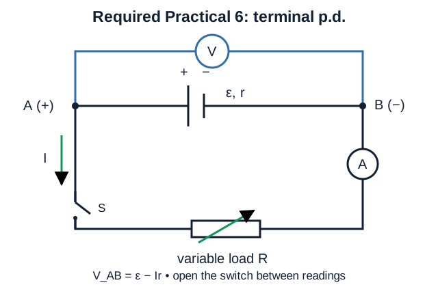
- Connect a cell, switch, ammeter and variable resistor in series; connect a voltmeter across the cell.
- Open the switch between readings to limit heating and cell discharge.
- Vary resistance and record several pairs of I and terminal V.
- Plot V against I. In V = ε − Ir, intercept = ε and gradient = −r.
Evaluation
Use a best-fit line rather than two adjacent points. Quote internal resistance as the magnitude of the gradient: V A⁻¹ = Ω. Use a large gradient triangle and steepest/shallowest acceptable lines through the uncertainty bars to estimate Δr. Estimate ε and its uncertainty from the intercept. Repeat readings and avoid currents large enough to change the cell temperature. The voltmeter measures the two distinct terminal nodes A and B shown above; it is not connected between two points on one return wire.
Generate the practical graph
Original exam-style practice
Questions and answers
1. Find the total resistance of 120 Ω and 220 Ω in parallel. [2 marks]
1/R = 1/120 + 1/220, so R = 77.6 Ω. It is correctly smaller than either branch resistance.
2. A 6.0 V cell has internal resistance 0.80 Ω and supplies a 4.0 Ω load. Find current and terminal p.d. [3 marks]
I = ε/(R+r) = 6.0/4.8 = 1.25 A. V = IR = 5.0 V.
3. A V–I graph has intercept 1.56 V and gradient −0.42 V A⁻¹. State ε and r. [2 marks]
ε = 1.56 V. Internal resistance is the magnitude of gradient: r = 0.42 Ω.
4. Design a divider whose output rises as light level rises. [3 marks]
Use an LDR as the top resistor and take Vout across the fixed bottom resistor. More light lowers LDR resistance, so a larger fraction of the supply p.d. appears across the fixed resistor.
5. State the physical principles behind the junction and loop rules. [2 marks]
The junction rule follows conservation of charge. The loop rule follows conservation of energy.
Specification checklist
AQA 7408 coverage
Letter suffixes in this checklist are PhysicsUK subdivisions for navigation. The official AQA references are the numbered sections above.
- 3.5.1.4(a) Calculate total resistance of resistors in series using RT = R1 + R2 + R3 + ...
- 3.5.1.4(b) Calculate total resistance of resistors in parallel using 1/RT = 1/R1 + 1/R2 + 1/R3 + ...
- 3.5.1.4(e) Apply current, voltage and resistance relationships in series and parallel circuits.
- 3.5.1.4(f) Analyse circuits with cells in series and identical cells in parallel.
- 3.5.1.4(g) Apply conservation of charge and conservation of energy in dc circuits.
- 3.5.1.5(a) Describe a potential divider used to supply a constant or variable potential difference from a power supply.
- 3.5.1.5(b) Describe potential dividers using variable resistors, thermistors and light-dependent resistors.
- 3.5.1.5(c) Design and analyse potential divider circuits to achieve specified outcomes.
- 3.5.1.5(d) Recognise that use of a potentiometer as a measuring instrument is not required.
- 3.5.1.6(a) Define electromotive force using ε = E/Q.
- 3.5.1.6(b) Use ε = I(R + r) or ε = IR + Ir for circuits with internal resistance.
- 3.5.1.6(c) Define terminal potential difference and electromotive force.
- 3.5.1.6(d) Perform calculations for circuits where internal resistance of the supply is not negligible.
Continue AQA Electricity
Current, charge and electrical energy · Resistance, resistivity and I–V characteristics · AQA 3.5 Electricity hub · Mechanics and materials · Waves · AQA Paper 1 revision · Physics calculation practice.
Written against AQA Physics 7408 section 3.5.1 and Required Practical 6. All questions are original.