Attempt each question before opening the hints. Show equations, substitutions, units and the reason for your method. The mark checklists below are PhysicsUK's own schemes.
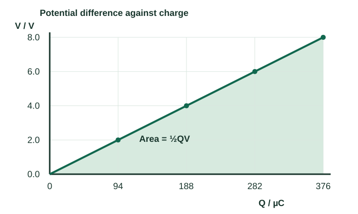
An ideal capacitor is tested at different potential differences. Its capacitance is constant.
Measured charge magnitude on either plate
V / V
Q / µC
0.0
0
2.0
94
4.0
188
6.0
282
8.0
376
(a) Define capacitance and calculate its value. [2]
(b) Use the area under the V–Q graph to find the stored energy at 8.0 V. [2]
(c) Explain the movement of electrons when the capacitor is charged from a battery. [1]
V is plotted against Q. The gradient is 1/C; the shaded area gives energy. Open the larger diagramSmall hint
Read the axes carefully: this graph has V vertically and Q horizontally.
Method hint
Use C = Q/V. For a straight line through the origin, the area under V against Q is a triangle with area ½QV. Convert microcoulombs to coulombs.
Complete worked solution and marks
Answer: C = 47 µF; stored energy = 1.5 × 10⁻³ J. Electrons move through the external circuit, leaving opposite charges on the plates.
Capacitance is charge stored on one plate per unit potential difference: C = Q/V. For this ideal capacitor it is the same at every non-zero row.
At 8.0 V, C = (376 × 10−6)/8.0 = 47 × 10−6 F = 47 µF. On this V–Q plot the slope is V/Q = 1/C, not C.
The area is W = ½ × 376 × 10−6 × 8.0 = 1.504 × 10⁻³ J ≈ 1.5 mJ. As more charge is separated, the p.d. rises; that is why QV would overestimate the energy by a factor of two.
The battery removes electrons from the plate connected to its positive terminal and supplies electrons to the other plate through the wires. Equal and opposite plate charges develop. Electrons do not cross the ideal insulating gap.
Check: A few tens of microfarads storing a few volts should store millijoules, not thousands of joules. V × C gives the stated 376 µC.
Mark checklist · 5 marks
1 mark — Defines capacitance as charge on one plate per unit p.d., or gives C = Q/V with quantities identified.
1 mark — Calculates 47 µF (4.7 × 10⁻⁵ F), including the unit.
1 mark — Uses triangular area ½QV with charge in coulombs. The equivalent ½CV² form earns this method mark when linked to the triangular area using Q = CV.
1 mark — Obtains 1.5 × 10⁻³ J, or 1.504 × 10⁻³ J before rounding. Correct-method error carried forward from a calculated C is allowed.
1 mark — Explains removal of electrons from one plate and supply to the other through the external circuit, giving opposite charges.
Common mistake: Taking the V–Q gradient as capacitance reverses the ratio. Use the axis labels: this slope has units V/C, so its reciprocal has units farads.
Try a changed context
The same ideal capacitor is charged to 4.0 V. Predict its charge and energy without recalculating its capacitance.
Check the transfer answer
Charge halves to 188 µC because Q ∝ V. Energy falls to one quarter: 0.376 mJ, because W ∝ V². C remains 47 µF.
Two initially uncharged ideal capacitors, 220 µF and 330 µF, are connected in parallel across a 9.0 V supply to store energy for a small flash circuit.
(a) Calculate the total capacitance, total stored charge and total stored energy. [4]
(b) The capacitors are discharged completely, then connected in series across the same supply. Calculate the p.d. across each capacitor when fully charged. [2]
Assume neither capacitor exceeds its voltage rating and leakage is negligible.
Parallel branches have the same p.d. In series, the initially neutral isolated junction leaves equal charge magnitudes. Open the larger diagramSmall hint
Which quantity is shared: p.d. in parallel, or charge magnitude in series?
Method hint
For parallel, add capacitances and use Q = CV and W = ½CV². For series, find Ctotal from reciprocal capacitances, then use the common Q and Vi = Q/Ci.
Complete worked solution and marks
Answer: Parallel: 550 µF, 4.95 mC and 22 mJ. Series: 5.4 V across 220 µF and 3.6 V across 330 µF.
Parallel capacitors have the same p.d. and their plate charges add: Ctotal = 220 + 330 = 550 µF = 550 × 10−6 F.
The total charge magnitude on the plates connected to one supply terminal is Qtotal = 550 × 10−6 × 9.0 = 4.95 × 10⁻³ C. This does not mean a net charge of 4.95 mC has been added to the whole capacitor pair: the opposite plates carry −4.95 mC.
The stored energy is W = ½ × 550 × 10−6 × 9.0² = 0.022275 J ≈ 22 mJ. This is the energy available in the capacitors; the flash circuit's useful output may be smaller.
For series, Ctotal = (220 × 330)/(220 + 330) = 132 µF. Hence the common charge magnitude is Q = 132 × 10−6 × 9.0 = 1.188 mC.
Divide the common charge by each capacitance: V220 = 1.188 × 10⁻³/(220 × 10−6) = 5.4 V;V330 = 3.6 V. The smaller capacitor has the larger p.d.
Check: Series capacitance 132 µF is smaller than either component. The series voltages add to the supply p.d., and their inverse-capacitance ratio is 330:220.
Mark checklist · 6 marks
1 mark — Adds parallel capacitances to obtain 550 µF.
1 mark — Obtains 4.95 mC, or 5.0 mC to two significant figures, using Q = CV.
1 mark — Uses W = ½CV² or sums ½CiV² for the two capacitors.
1 mark — Obtains 0.022 J (22 mJ); 0.022275 J is accepted before rounding. Correct-method carry-forward from C is allowed.
1 mark — Uses equal series charge to obtain 5.4 V across 220 µF; a correct inverse-capacitance voltage ratio is an accepted method.
1 mark — Obtains 3.6 V across 330 µF; the two p.d.s sum to 9.0 V. Carry-forward by subtracting the candidate's first p.d. from 9.0 V is allowed if the series model is correct.
Common mistake: Using resistor combination rules gives the wrong capacitor result. Start from what the circuit shares: parallel gives equal V, while initially uncharged ideal series capacitors acquire equal |Q|.
Exam technique: OCR's June 2024 H556/02 report says that most candidates answered Q4 correctly; the most common distractor came from combining capacitors as if they were resistors. State the shared quantity before choosing the combination rule.
Try a changed context
How much energy does the series pair store at 9.0 V, and why is it less than the parallel pair?
Check the transfer answer
W = ½ × 132 × 10⁻⁶ × 9.0² = 5.346 mJ ≈ 5.3 mJ. At fixed supply p.d., W is proportional to total capacitance; the series capacitance is smaller. Do not assume energy is unchanged when the capacitors are discharged and reconnected.
An initially uncharged 220 µF capacitor charges from a 12.0 V ideal supply through 100 kΩ. After 15.0 s, a switch disconnects the supply and connects the capacitor across a separate 47.0 kΩ resistor. Neglect leakage and switch contact resistance.
(a) Calculate the capacitor p.d. and charging current just before switching. [3]
(b) Calculate the current immediately after switching, with its direction, and the capacitor p.d. 5.00 s after switching. Explain which capacitor quantity is continuous at the switch. [3]
For the current sign, take the original charging sense through the capacitor as positive. The 5.00 s interval starts at the switching event.
Small hint
The discharge begins from the p.d. actually reached after 15 seconds, rather than from the supply p.d.
Method hint
Use charging τ = 100 kΩ × 220 µF and Vc = Vs(1 − exp(−t/τ)). Before the switch, I = (Vs − Vc)/R. After it, use the new resistance and Vc at switching as Vi in Vi exp(−t/RdC).
Complete worked solution and marks
Answer: Before switching: 5.93 V and +60.7 µA. Immediately after: −126 µA in the discharge sense. After 5.00 s: 3.66 V. Charge and capacitor p.d. are continuous in this finite-resistance model.
Convert the prefixes and obtain τcharge = 100 × 10³ × 220 × 10−6 = 22.0 s.
At 15.0 s, Vi = 12.0(1 − e−15.0/22.0) = 5.9316… V. Keep extra digits for the following calculations.
The resistor has the remaining supply p.d.: Ibefore = (12.0 − 5.9316…)/(100 × 10³) = +60.7 µA. Dividing Vc by the charging resistor would use the wrong component p.d.
Charge cannot change instantaneously through a finite resistor, so Q and Vc = Q/C are continuous. The new discharge time constant is τdischarge = 47.0 × 10³ × 220 × 10−6 = 10.34 s.
The discharge current is opposite to the chosen charging sense: Iafter = −Vi/Rd = −5.9316…/(47.0 × 10³) = −126 µA. A signed circuit sketch or an explicit discharge direction is equally useful.
After 5.00 s of discharge, VC = 5.9316… e−5.00/10.34 = 3.6574… V ≈ 3.66 V. The elapsed discharge time is 5.00 s, not 20.0 s.
Check: The smaller discharge resistor allows a larger initial current magnitude, even though the capacitor was only partly charged. The p.d. then falls below 5.93 V.
Mark checklist · 6 marks
1 mark — Finds charging RC = 22.0 s with prefixes converted correctly.
1 mark — Uses the charging exponential to obtain Vc = 5.93 V.
1 mark — Uses resistor p.d. 12.0 − Vc to obtain charging current +60.7 µA. Correct-method carry-forward from Vc is allowed.
1 mark — States charge or capacitor p.d. is continuous at switching and uses the new discharge RC = 10.34 s.
1 mark — Obtains magnitude 126 µA with an explicit discharge direction or negative sign under the stated convention. Carry-forward from Vi is allowed.
1 mark — Uses Vi exp(−5.00/10.34) to obtain 3.66 V. Correct-method carry-forward from Vi or discharge RC is allowed.
Common mistake: A switch does not automatically reset capacitor voltage to zero or 12 V. Carry the actual stored charge into the next circuit stage, then reset the elapsed-time origin.
Exam technique: The capacitor-versus-resistor p.d. distinction is also discussed in AQA's June 2024 Paper 2 report, Q02.3. This is transferable circuit reasoning; it does not imply an official OCR allocation for this original question.
Try a changed context
Predict the p.d. after 10.0 s of discharge. Is it half the value after 5.00 s?
Check the transfer answer
Vc = 5.9316… exp(−10.0/10.34) = 2.26 V. Equal 5-second intervals multiply voltage by the same ratio exp(−5/10.34) ≈ 0.617; they do not halve it unless 5 seconds equals the half-life.
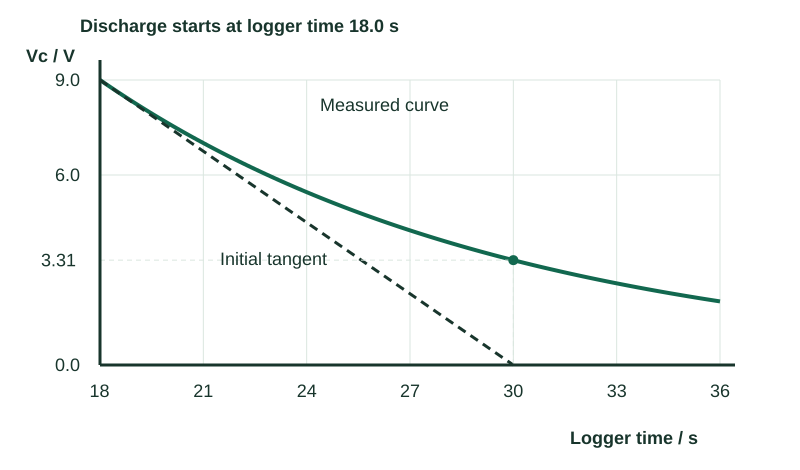
A logger records capacitor p.d. during discharge through a 120 kΩ resistor. Discharge begins at logger time 18.0 s. The tangent at that instant passes through (18.0 s, 9.0 V) and (30.0 s, 0 V); the latter is a tangent intercept, not a measured zero voltage.
Measured capacitor p.d. during discharge
Logger time / s
Vc / V
18.0
9.000
21.0
7.009
24.0
5.459
27.0
4.251
30.0
3.311
33.0
2.579
36.0
2.008
(a) Use the initial tangent and circuit equations to determine capacitance. Explain why the gradient must be the initial one. [4]
(b) Determine the time constant from the voltage data. [2]
The dashed tangent reaches zero at 30 s; the capacitor's measured p.d. there is still 3.31 V. Open the larger diagramSmall hint
A gradient uses a change in time. The logger started counting before discharge began.
Method hint
Initially |I| = Vi/R and |I| = C|dVc/dt|. Calculate the tangent gradient from its two points. For τ, find where Vc = Vi/e, then subtract the discharge starting time.
Complete worked solution and marks
Answer: Initial gradient = −0.75 V s⁻¹; C = 100 µF; time constant = 12.0 s, from logger time 30.0 − 18.0 s.
At the discharge start the resistor p.d. is 9.0 V. Its current magnitude is |Ii| = 9.0/(120 × 10³) = 75 µA. A later tangent would belong to a smaller current and voltage.
The initial tangent gives dVC/dt ≈ (0 − 9.0)/(30.0 − 18.0) = −0.75 V s−1. Use a large triangle along the tangent rather than a chord between two points on the curve.
For constant C, differentiating Q = CV gives dQ/dt = C dV/dt. Therefore C = |Ii|/|dV/dt| = (75 × 10−6)/0.75 = 100 µF. The initial gradient is required because the current value used is the initial current.
At one time constant, Vc = Vi/e = 9.0/e = 3.31 V. The data place this at logger time 30.0 s. Hence τ = 30.0 − 18.0 = 12.0 s. As a separate check, RC = 120 × 10³ × 100 × 10−6 = 12.0 s.
Check: Multiplying R by the graph-derived C reproduces 12 seconds. An answer of 30 seconds includes the 18 seconds before discharge began.
Mark checklist · 6 marks
1 mark — Selects the initial tangent and explains it must match the initial current 9.0/R.
1 mark — Calculates the tangent gradient −0.75 V s⁻¹, or magnitude 0.75 V s⁻¹ with discharge identified.
1 mark — Links I to charge rate and Q = CV to justify |I| = C|dV/dt|, or gives the equivalent discharge derivative.
1 mark — Obtains C = 100 µF (1.0 × 10⁻⁴ F). Correct-method carry-forward from a measured initial gradient is allowed.
1 mark — Uses 9.0/e = 3.31 V and reads the corresponding logger time 30.0 s from the data; an equivalent ratio/log method using data is accepted.
1 mark — Subtracts the start time to obtain elapsed time constant 12.0 s. A calculation using RC alone does not earn the data-reading mark.
Common mistake: The tangent intercept is not the time when the capacitor is empty. The exponential curve remains above zero; the intercept can help identify τ only because it is the initial tangent.
Exam technique: AQA's June 2024 Paper 2 report, Q02.1–02.2, stresses the initial gradient and elapsed time from the start of discharge. Here those ideas are applied to a new graph and different values.
Try a changed context
Find the voltage ratio between logger times 21 s and 24 s, and between 30 s and 33 s. What does the agreement show?
Check the transfer answer
5.459/7.009 ≈ 0.779 and 2.579/3.311 ≈ 0.779. Equal three-second intervals have the same multiplicative ratio, consistent with exponential decay. Equal voltage differences would instead indicate a straight line.
Question 5 · Practical investigation · 6 marks
Measure capacitance from a discharge
Specification: 6.1.3(a)(ii), 6.1.3(b), 6.1.3(c)
Describe how to determine the capacitance of an unknown capacitor by recording its discharge through a measured resistor. You have a low-voltage dc supply, a suitable switch, a resistor, a resistance meter and a high-input-resistance voltage logger.
Your answer should include the circuit and switching procedure, measurements, a suitable graph and how its gradient gives capacitance, and one justified improvement or source of systematic error. [6]
Small hint
The logger must measure p.d. across the capacitor without providing a significant extra discharge path.
Method hint
Record V against elapsed discharge time. Take ln(V/1 V) so the graph quantity is dimensionless; the gradient of ln(V/1 V) against t is −1/(RC). Identify why input resistance and component ratings matter.
Complete worked solution and marks
Answer: Charge safely, isolate the supply, log Vc during discharge through measured R, and plot ln(Vc/1 V) against elapsed t. With gradient m, C = −1/(Rm), after accounting for any significant logger loading.
Measure R with the supply disconnected. Connect the voltage logger across the capacitor. Use a switch arrangement that charges the capacitor from a low-voltage supply and then disconnects the supply while completing a discharge loop through R. The resistor is not bypassed during discharge.
Respect capacitor voltage and polarity ratings; limit charging current, and discharge through a resistor before handling or reconnecting the component. Select R so RC is long enough to resolve many readings. A short direct discharge could damage the capacitor or switch.
Charge to a reproducible starting p.d. Vi. Begin logging and take the switching event as elapsed t = 0. Sample often enough to describe the early decay; record readings across several time constants while they remain above the logger's resolution/noise floor. Repeat the discharge.
Plot y = ln(Vc/1 V) against elapsed t in seconds. From Vc = Vi e−t/RC, y = ln(Vi/1 V) − t/(RC). The best-fit straight-line gradient m has units s−1 and is negative.
Use C = −1/(Rm). Compare repeat gradients and quote sensible precision. A worst-fit gradient range can estimate uncertainty in C alongside uncertainty in R.
The logger's finite input resistance is in parallel with the discharge resistor. If it is not much larger than R, use Reff = (1/R + 1/Rin)−1, or choose a higher-input-resistance logger. Ignoring that extra path makes the measured decay faster and underestimates C when R is used.
Check: A negative gradient must produce a positive capacitance. For example, R = 100 kΩ and m = −0.050 s⁻¹ would give C = 200 µF.
Mark checklist · 6 marks
1 mark — Describes a valid charge/discharge switch circuit with logger across C and supply disconnected during discharge through R.
1 mark — Measures R and specifies safe capacitor polarity/voltage and a current-limited charge/discharge procedure.
1 mark — Records multiple Vc–time readings with switching as the time origin and an interval appropriate to RC; repeated runs improve reliability.
1 mark — Plots ln(Vc/1 V) against time and fits a straight line, linking its gradient to −1/(RC). Standard ln V shorthand is accepted when the voltage unit is fixed.
1 mark — Uses C = −1/(Rm), or an equivalent clearly explained fit to determine C.
1 mark — Gives a justified contextual improvement/error, such as logger loading with its effect, avoiding low-voltage noise, or gradient/repeat uncertainty. A generic 'repeat to be accurate' is insufficient.
Common mistake: Plotting V against t and expecting a straight line loses the exponential relationship. Transform the voltage, or fit an exponential directly and explain what its fitted time constant means.
Try a changed context
R = 1.00 MΩ and the logger input resistance is also 1.00 MΩ. If you ignore the logger, what fraction of the true C will you infer?
Check the transfer answer
Reff = 0.500 MΩ. The decay time constant is Reff Ctrue, so Cinferred = τ/R = 0.500 Ctrue. The inferred capacitance is half the true value, under the ideal parallel-resistance model.
A 1000 µF capacitor, initially at 6.0 V, discharges through 68 kΩ.
(a) Calculate the time for its stored energy to fall to 10% of its starting energy. [4]
(b) The experiment is repeated from 6.0 V with R doubled and C unchanged. Explain the effect on that time and on the initial discharge current magnitude. [2]
Assume fixed capacitance and resistance, negligible leakage, and no extra discharge path.
Small hint
Energy is proportional to the square of voltage, rather than to voltage itself.
Method hint
Combine W = ½CV² with V/Vi = exp(−t/RC). Then W/Wi = exp(−2t/RC). For the comparison, use τ = RC and |Ii| = Vi/R.
Complete worked solution and marks
Answer: Time = 78 s (78.29 s before rounding). Doubling R doubles this time to 157 s to three significant figures (156.58 s before final rounding; 1.6 × 10² s to two significant figures) and halves the initial current magnitude from 88 µA to 44 µA.
The time constant is τ = 68 × 10³ × 1000 × 10−6 = 68 s. The initial energy is ½ × 0.001 × 6.0² = 0.018 J, although this value is not required for the ratio method.
Because C stays fixed, W/Wi = (V/Vi)² = e−2t/RC. At 10% energy, V/Vi = √0.10 ≈ 0.316, not 0.10.
Take logs: ln(0.10) = −2t/68;t = −(68/2) ln(0.10) = 78.2879… s ≈ 78 s.
Doubling R doubles RC. The same fractional energy change therefore takes twice as long: 156.576… s. With the same starting voltage, |Ii| = Vi/R. It falls from 6.0/(68 × 10³) ≈ 88 µA to about 44 µA. The initial stored energy is unchanged because C and Vi are unchanged.
Check: At 78.29 seconds, voltage is about 1.90 V. Squaring 1.90/6.0 gives about 0.10. Treating 10% energy as 10% voltage would give a time twice as large.
Mark checklist · 6 marks
1 mark — Calculates RC = 68 s with the capacitance prefix converted correctly.
1 mark — Uses W/Wi = (V/Vi)² or the equivalent energy exponential, so the target voltage fraction is √0.10.
1 mark — Correctly rearranges the exponential using a logarithm: t = −RC ln(0.10)/2, or an equivalent voltage-ratio route.
1 mark — Obtains 78 s; 78.29 s is accepted before rounding. Correct-method carry-forward from RC is allowed.
1 mark — States time doubles and justifies it by RC doubling, with C unchanged.
1 mark — States initial current magnitude halves and justifies it by Vi/R with Vi unchanged.
Common mistake: Voltage, charge and current have the same exponential time constant here, but energy depends on their square. Always connect the requested quantity to the measured variable before using a percentage.
Try a changed context
A spreadsheet models the same discharge with Qnext = Q − (Q/RC)Δt and Δt = 10 s. Starting from Q = 6.0 mC, find Q after one step. Compare it with the exponential prediction.
Check the transfer answer
Euler step: Qnext = 6.0(1 − 10/68) = 5.12 mC. Exact exponential: 6.0 exp(−10/68) = 5.18 mC. The step model overestimates charge loss because it holds the initial rate constant during the step, while the real magnitude of the rate decreases. Reducing Δt compared with RC reduces this approximation error. This extension addresses 6.1.3(d).
Use the simulation to check your predictions
Set R and C, predict RC, then charge from empty. Pause near one time constant: voltage and charge should reach about 63.2% of their final values. Switch to the resistor before full charge and use the measured switching voltage as the new starting voltage. During discharge, predict the energy fraction before checking the voltage: half the voltage means one quarter of the initial energy.
This starting set addresses capacitance and electron flow, series/parallel calculations, energy, resistor-capacitor circuits, time constants, exponential equations, discharge graphs and a discharge investigation. It introduces spreadsheet modelling in a transfer task. Further questions are planned for experimentally investigating series/parallel combinations and evaluating spreadsheet step size in detail. Six questions are not a complete assessment of every outcome in section 6.1.
PhysicsUK's combination feedback uses the capacitor-versus-resistor error discussed in OCR H556/02 June 2024, Q4 (report page 8). The initial-tangent, elapsed-time and resistor-versus-capacitor-voltage advice uses AQA 7408/2 June 2024, Q02.1–02.3 (report pages 3–4); the underlying physics transfers to OCR, while the marks here are our own. These inspected examples inform technique; they are not a multi-year frequency study.