
AQA A-level Physics 7408 · Paper 2 · 3.7.5.3–3.7.5.6
Electromagnetic induction, alternating currents and transformers
Link changing magnetic flux to induced emf, interpret sinusoidal and oscilloscope data, then apply transformer and transmission equations. Diagnose the phase traps, use the three-mode simulator and finish with a 42-mark assessment.
Content diagnostic
Can you separate flux from rate of change?
Learning route
One energy-transfer chain
Describe linkage
Resolve the field perpendicular to a coil and calculate Φ and NΦ with the correct angle.
Change linkage
Use Faraday’s law for the magnitude and Lenz’s law for the direction of an induced emf.
Analyse AC
Move between peak, rms, peak-to-peak, period, frequency and oscilloscope divisions.
Transfer power
Use transformer ratios and efficiency, then quantify why high-voltage transmission reduces I²R loss.
Magnetic flux and flux linkage
Area means area perpendicular to the field
Magnetic flux
This form applies when B is normal to the area. One weber is one tesla metre squared.
Rotated N-turn coil
θ is the angle between B and the normal to the coil. At θ = 0°, linkage is maximum; at θ = 90°, it is zero.
Faraday and Lenz
Magnitude from rate; direction from opposition
Faraday’s law
The mean induced emf equals the rate of change of flux linkage. A larger number of turns, larger flux change or shorter time produces a larger magnitude.
Lenz’s law
The induced emf has a direction such that its effects oppose the change that produced it. The opposition is to the change in flux linkage, not automatically to the field or motion in isolation.
Ways to induce an emf
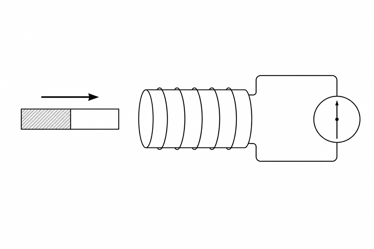
- Move a magnet relative to a coil.
- Change current in a neighbouring coil.
- Move a conductor across a magnetic field.
- Rotate a coil so its orientation and linkage change.
Motional emf from Faraday’s law
- A rod of length l moving distance vΔt sweeps area ΔA = lvΔt.
- For perpendicular geometry, the flux change is ΔΦ = BΔA = BlvΔt.
- Divide by Δt to obtain ε = Blv.
Rotating-coil generator
Flux linkage and emf are a quarter-cycle apart
Uniform rotation makes the angle θ = ωt. Linkage is a cosine curve.
Faraday’s law differentiates the linkage; the emf is sinusoidal with peak value ε₀ = BANω.
- At maximum or minimum linkage, its gradient is zero, so emf is zero.
- At zero linkage, the gradient magnitude is maximum, so |ε| is maximum.
- Increasing B, A, N or ω increases peak emf in direct proportion.
- Slip rings carry the alternating output to stationary brushes.
Useful simulation
Induction, oscilloscope and transformer explorer
In generator mode, move the angle marker and compare linkage with emf. In oscilloscope mode, change time base and y-gain before calculating values. In transformer mode, test the turns ratio, efficiency and the inverse-square fall in cable loss as transmission voltage rises.
Alternating currents and oscilloscopes
Translate the waveform before calculating
Sinusoidal relationships
Peak-to-peak voltage is Vₚₚ = 2V₀. The rms value gives the same mean heating power in a resistor as the same value of steady dc.
Time and frequency
For v = V₀ sin ωt, angular frequency ω = 2πf. A 230 V rms sinusoidal mains supply has peak voltage about 325 V and peak-to-peak voltage about 650 V.
Oscilloscope controls and measurements
| Control or reading | What it changes | Exam calculation |
|---|---|---|
| Y-gain or volts per division | Vertical scale; a smaller V/div makes the same signal taller. | Voltage = vertical divisions × V/div. |
| Time base or time per division | Horizontal scale; a smaller time/div spreads a cycle across more divisions. | Period = horizontal divisions × time/div, then f = 1/T. |
| Vertical position | Moves the trace without changing the signal amplitude. | Use the zero reference before measuring dc level. |
| Trigger | Stabilises a repeating waveform on the screen. | It does not alter the signal frequency. |
| AC/DC selection | Allows alternating waveforms or steady levels to be displayed and measured. | A steady dc input gives a displaced horizontal line. |
Transformers, losses and transmission
High voltage is valuable because current becomes small
Turns and voltage
Nₛ > Nₚ gives a step-up transformer. Nₛ < Nₚ gives a step-down transformer. A transformer requires changing flux, so it operates with ac rather than steady dc.
Efficiency
Use consistent rms current and voltage values. Efficiency can be written as a ratio or percentage and cannot exceed 1 or 100%.
Where transformer energy goes
- Eddy currents: changing core flux induces circulating currents, which heat the core. Insulated laminations interrupt large loops.
- Winding resistance: current causes I²R heating in copper wire.
- Hysteresis: repeatedly magnetising the core transfers energy to internal energy.
- Flux leakage, vibration and sound: not all input energy reaches the secondary circuit.
National Grid reasoning
- For transmitted power P, line current I = P/V.
- Step up V so the same power needs a smaller I.
- Cable heating is Pₗₒₛₛ = I²R, so reducing current by ten reduces loss by one hundred.
- Step down the voltage near consumers for safe, useful distribution.
Misconception repair
Statements that cost marks
| Tempting statement | Why it fails | Repair |
|---|---|---|
| “Flux is BA cos θ where θ is to the coil.” | The reference line is ambiguous. | State that θ is between B and the normal to the coil. |
| “A large flux produces a large emf.” | Emf depends on rate of change, not flux alone. | Use ε = −d(NΦ)/dt. |
| “Lenz’s law opposes the magnetic field.” | It opposes the change in flux linkage. | Describe whether the linkage is increasing or decreasing first. |
| “At zero flux, emf is zero.” | The flux-linkage curve is steepest there. | Zero linkage corresponds to maximum |ε| in a rotating coil. |
| “230 V mains is its peak voltage.” | 230 V is an rms value. | V₀ = √2Vᵣₘₛ ≈ 325 V. |
| “Peak-to-peak equals peak.” | It spans positive peak to negative peak. | Vₚₚ = 2V₀. |
| “The time base changes frequency.” | It changes only how the signal is displayed. | The source sets frequency; time/div sets horizontal scale. |
| “Transformers save power by increasing it.” | They change voltage and current; real output power is smaller. | Use efficiency and explain reduced grid loss through smaller I. |
Original exam-style assessment
42 marks across every specification leaf
Attempt the questions without opening the mark schemes. Show substitutions, keep the angle convention explicit and use rms or peak values exactly as requested.
1. A 180-turn rectangular coil has area 0.0120 m² and is in a uniform magnetic field of flux density 0.350 T. The angle between the magnetic field and the normal to the coil is 38.0°. Calculate the magnetic flux through one turn and the flux linkage of the coil. State why the angle in the cosine term is not the angle between the field and the plane of the coil.[4 marks]
Mark scheme
- (M1) Uses Φ = BA cos θ with θ measured from the normal to the coil.
- (A1) Φ = 0.350 × 0.0120 × cos 38.0° = 3.31 × 10⁻³ Wb.
- (A1) NΦ = 180 × 3.31 × 10⁻³ = 0.596 Wb turns.
- (B1) Magnetic flux uses the component of B perpendicular to the coil area, so θ is between B and the area normal, not the coil plane.
Exact AQA content: 3.7.5.3(a), 3.7.5.3(b), 3.7.5.3(c)
2. A bar magnet is withdrawn from a 120-turn coil. The magnetic flux through each turn falls from 3.20 × 10⁻³ Wb to 0.800 × 10⁻³ Wb in 0.0400 s. Calculate the magnitude of the mean induced emf. Explain how Lenz’s law determines the direction of the induced current.[4 marks]
Mark scheme
- (B1) The moving magnet changes the magnetic flux linking the coil, so an emf is induced.
- (M1) Applies Faraday’s law using |ε| = N|ΔΦ|/Δt.
- (A1) |ε| = 120 × (3.20 − 0.800) × 10⁻³ / 0.0400 = 7.20 V.
- (B1) The induced current produces a magnetic effect that opposes the decrease in flux, not the motion without reference to the flux change.
Exact AQA content: 3.7.5.4(a), 3.7.5.4(b), 3.7.5.4(c)
3. A straight conductor of length 0.240 m moves at 3.80 m s⁻¹ perpendicular to a uniform 0.520 T magnetic field. Its length is also perpendicular to its velocity. Starting from the area swept out in time Δt, obtain the expression for the induced emf and calculate its magnitude.[4 marks]
Mark scheme
- (M1) In time Δt the conductor sweeps area ΔA = lvΔt, so the flux change is ΔΦ = BlvΔt.
- (M1) Substitutes into ε = ΔΦ/Δt to obtain ε = Blv for one conductor.
- (A1) ε = 0.520 × 0.240 × 3.80 = 0.474 V.
- (B1) The emf would reverse if either the motion direction or magnetic-field direction alone were reversed.
Exact AQA content: 3.7.5.4(d), 3.7.5.4(e)
4. A 120-turn coil of area 0.00650 m² rotates at 40.0 Hz in a uniform magnetic field of flux density 0.180 T. Calculate its angular speed and peak induced emf. Calculate the instantaneous emf when ωt = 30.0° and state the flux-linkage condition when the emf is zero.[4 marks]
Mark scheme
- (A1) ω = 2πf = 251 rad s⁻¹.
- (M1) Uses ε₀ = BANω.
- (A1) ε₀ = 35.3 V and ε = 35.3 sin 30.0° = 17.6 V.
- (B1) The emf is zero when flux linkage is at a maximum or minimum because its instantaneous rate of change is zero.
Exact AQA content: 3.7.5.3(c), 3.7.5.4(d), 3.7.5.4(f)
5. An alternating current is described by i = 4.80 sin(314t), where i is in amperes and t is in seconds. State the peak current, calculate the frequency and calculate the rms current. State what the negative half-cycle represents.[4 marks]
Mark scheme
- (B1) Peak current I₀ = 4.80 A.
- (A1) f = ω/(2π) = 314/(2π) = 50.0 Hz.
- (A1) Iᵣₘₛ = I₀/√2 = 3.39 A.
- (B1) The negative half-cycle means the conventional current is in the opposite direction to that chosen as positive.
Exact AQA content: 3.7.5.5(a), 3.7.5.5(b), 3.7.5.5(c)
6. The mains supply is 230 V rms and sinusoidal. Calculate its peak voltage and peak-to-peak voltage. State the physical meaning of the quoted rms value.[3 marks]
Mark scheme
- (A1) V₀ = √2 × 230 = 325 V.
- (A1) Vₚₚ = 2V₀ = 651 V, accepting 650 V to appropriate rounding.
- (B1) 230 V rms produces the same mean power in a resistor as a steady 230 V dc supply.
Exact AQA content: 3.7.5.5(b), 3.7.5.5(c), 3.7.5.5(d)
7. A sinusoidal oscilloscope trace has a peak-to-peak height of 5.60 divisions and one complete cycle occupies 3.20 horizontal divisions. The y-gain is 2.00 V div⁻¹ and the time base is 5.00 ms div⁻¹. Calculate the peak-to-peak voltage, peak voltage, period and frequency. State one control change that makes the trace taller without changing the input signal.[5 marks]
Mark scheme
- (A1) Vₚₚ = 5.60 × 2.00 = 11.2 V.
- (A1) V₀ = Vₚₚ/2 = 5.60 V.
- (A1) T = 3.20 × 5.00 ms = 16.0 ms.
- (A1) f = 1/T = 62.5 Hz.
- (B1) Select a smaller volts-per-division or greater y-gain setting; changing time base does not make the trace taller.
Exact AQA content: 3.7.5.5(a), 3.7.5.5(e), 3.7.5.5(f)
8. A transformer has 1200 turns on its 240 V primary and 90 turns on its secondary. The primary current is 2.00 A and the secondary current is 23.0 A. Calculate the secondary voltage and the transformer efficiency.[4 marks]
Mark scheme
- (M1) Uses Nₛ/Nₚ = Vₛ/Vₚ.
- (A1) Vₛ = 240 × 90/1200 = 18.0 V.
- (M1) Uses efficiency = IₛVₛ/(IₚVₚ).
- (A1) Efficiency = (23.0 × 18.0)/(2.00 × 240) = 0.863 or 86.3%.
Exact AQA content: 3.7.5.6(a), 3.7.5.6(b)
9. Explain why a transformer core is laminated rather than made from one solid block. Then identify one other cause of transformer inefficiency and explain how it transfers energy away from the useful output.[4 marks]
Mark scheme
- (B1) Changing magnetic flux in a conducting core induces emfs and circulating eddy currents in the core.
- (B1) Eddy currents cause I²R heating of the core and transfer electrical energy to internal energy.
- (B1) Insulated laminations break up the current loops or increase their resistance, reducing eddy currents.
- (B1) Identifies and explains another valid loss, such as winding I²R heating, hysteresis heating, flux leakage, vibration or sound.
Exact AQA content: 3.7.5.6(c), 3.7.5.6(d)
10. A power station transmits 6.00 MW through cables with total resistance 4.00 Ω. Calculate the line current and power loss when the transmission voltage is 25.0 kV. Repeat both calculations for 250 kV. Explain why the National Grid uses step-up transformers before transmission.[6 marks]
Mark scheme
- (M1) Uses I = P/V and Pₗₒₛₛ = I²R.
- (A1) At 25.0 kV, I = 6.00 × 10⁶ / 25.0 × 10³ = 240 A.
- (A1) At 25.0 kV, Pₗₒₛₛ = 240² × 4.00 = 2.30 × 10⁵ W or 230 kW.
- (A1) At 250 kV, I = 24.0 A.
- (A1) At 250 kV, Pₗₒₛₛ = 24.0² × 4.00 = 2.30 × 10³ W or 2.30 kW.
- (B1) For the same transmitted power, stepping up voltage reduces current, so I²R heating and wasted energy fall by the square of the current reduction.
Exact AQA content: 3.7.5.6(e), 3.7.5.6(f)
Specification fidelity
The exact AQA 7408 coverage
This resource teaches every assessable leaf in sections 3.7.5.3 to 3.7.5.6. It deliberately follows the specification boundary and does not require structural details of the oscilloscope.
- 3.7.5.3(a) Define magnetic flux Φ = BA where B is normal to area A.
- 3.7.5.3(b) Define flux linkage NΦ.
- 3.7.5.3(c) Use NΦ = BAN cosθ for a rectangular coil rotated in a magnetic field.
- 3.7.5.4(a) Describe simple electromagnetic induction phenomena.
- 3.7.5.4(b) State and apply Faraday's law.
- 3.7.5.4(c) State and apply Lenz's law.
- 3.7.5.4(d) Use induced emf = rate of change of flux linkage, ε = NΔΦ/Δt.
- 3.7.5.4(e) Apply electromagnetic induction to a straight conductor moving in a magnetic field.
- 3.7.5.4(f) Use ε = BANω sinωt for a coil rotating uniformly in a magnetic field.
- 3.7.5.5(a) Analyse sinusoidal voltages and currents.
- 3.7.5.5(b) Use rms, peak and peak-to-peak values for sinusoidal waveforms.
- 3.7.5.5(c) Use Irms = I0/√2 and Vrms = V0/√2.
- 3.7.5.5(d) Calculate peak and peak-to-peak values for mains electricity.
- 3.7.5.5(e) Use an oscilloscope as a dc and ac voltmeter, to measure time intervals and frequencies, and to display ac waveforms.
- 3.7.5.5(f) Know oscilloscope control operation without needing structural details of the instrument.
- 3.7.5.6(a) Use transformer equation Ns/Np = Vs/Vp.
- 3.7.5.6(b) Use transformer efficiency = IsVs/(IpVp).
- 3.7.5.6(c) Explain production of eddy currents.
- 3.7.5.6(d) Explain causes of transformer inefficiency.
- 3.7.5.6(e) Explain transmission of electrical power at high voltage.
- 3.7.5.6(f) Calculate power loss in transmission lines.
Keep building AQA Paper 2 connections
Return to the AQA 3.7 fields module hub or revisit magnetic fields and charged particles for the field and force ideas that precede induction. Connect transformer current, power and efficiency to circuits, e.m.f. and internal resistance, and compare stored electrical energy with capacitors, charge and energy. Continue through the AQA Paper 2 revision hub, problem-solving practice and MCQ practice.
Written against all 21 AQA Physics 7408 points in sections 3.7.5.3–3.7.5.6. Questions, values and mark schemes are original. The induction stimulus is an original generated PNG without assessed text; the interactive model is the original PhysicsUK three-mode induction, AC and transformer explorer.