
OCR A H556 · Module 4 · Section 4.2
Energy, power and resistance
Connect energy per charge to real component behaviour. Explore I–V characteristics, design a resistivity investigation and choose power equations from the information given.
How to learn actively
Use the graph as evidence
Sketch first
Predict the graph shape and label both axes before opening an answer.
Measure
Use a point, gradient or simulated reading only when the physics justifies it.
Explain
Link the changing temperature, carrier density or dimensions to the measured resistance.
Part 1
Circuit diagrams, potential difference and e.m.f.
Potential difference
Potential difference is the energy transferred from each coulomb of charge by a component. One volt is one joule per coulomb.
Electromotive force
E.m.f. is the energy supplied to each coulomb by a source. It is not a mechanical force. The unit is also the volt.
Standard circuit language
Use recognised OCR circuit symbols, join wires clearly and place an ammeter in series. A voltmeter measures between two points, so it is connected in parallel with the component.
Energy transfer
Use for charge moving through a potential difference.
Source energy
Use for energy supplied by a source.
Accelerated particle
Equate electrical energy transferred to kinetic energy gained when appropriate.
Part 2
Resistance and Ohm’s law
This equation defines resistance at an operating point. It can be used for ohmic and non-ohmic components.
Ohm’s law: current is directly proportional to potential difference for a conductor when temperature and other physical conditions remain constant.
Interactive laboratory
I–V characteristic explorer
Predict the shape before changing voltage
Select a component, predict its curve and then move the operating voltage. The graph axes stay fixed so changes remain visually meaningful.
| Component | Graph evidence | Physical explanation |
|---|---|---|
| Ohmic resistor | Straight line through the origin at constant temperature. | Resistance is constant. |
| Filament lamp | Gradient decreases as |V| rises. | The filament heats, so its resistance increases. |
| Diode or LED | Very small reverse current; rapid forward-current rise after a threshold. | Current passes mainly in one direction. |
| NTC thermistor | At higher temperature, a given V produces a larger I. | Resistance falls as temperature rises. |
Practical techniques
Investigating electrical characteristics
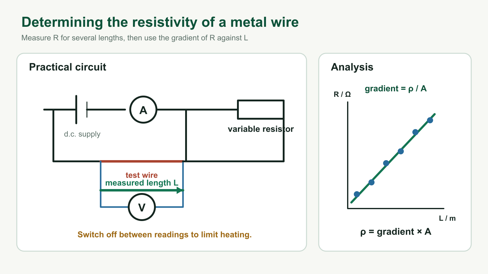
- Connect the ammeter in series and the voltmeter in parallel with the test component.
- Use a variable resistor or variable d.c. supply to change the p.d. safely.
- Record paired V and I readings. Reverse the supply polarity to obtain negative values when appropriate.
- Plot I on the vertical axis against V on the horizontal axis when asked for an I–V characteristic.
Part 3
Resistance and resistivity
Resistance depends on material and dimensions. Resistivity ρ describes the material itself at a stated temperature; changing only the wire’s length or diameter does not change its resistivity.
Measure diameter at several positions and orientations with a micrometer. Convert the diameter to metres before calculating area.
Wire designer
Predict the scale factor first. Doubling diameter changes area—and therefore resistance—by a factor of four.
Determining resistivity
Measure resistance for several lengths of the same uniform wire. A graph of R against L has gradient ρ/A, so ρ = gradient × A. Keep temperature as steady as possible because resistivity depends on temperature.
Temperature effects
For a metal, increasing temperature increases lattice vibration and usually increases resistivity. In a semiconductor or NTC thermistor, heating releases more mobile charge carriers, so resistivity and resistance decrease.
An LDR’s resistance decreases as light intensity increases.
Part 4
Electrical power, energy and cost
Any component
Power is energy transferred per second.
Using resistance
Useful when current and resistance are known.
Using resistance
Useful when p.d. and resistance are known.
A kilowatt-hour is a unit of energy: 1 kWh = 3.6 × 10⁶ J.
Energy-cost calculator
Original exam-style practice
Apply the evidence
Q1. State Ohm’s law precisely.
The current through a conductor is directly proportional to the potential difference across it, provided temperature and other physical conditions remain constant.
Q2. A lamp operates at 12 V and 0.40 A. Calculate its resistance and power.
R = V/I = 12/0.40 = 30 Ω. P = IV = 0.40 × 12 = 4.8 W.
Q3. A wire’s length triples and diameter halves. Its material and temperature do not change. Find the resistance scale factor.
Halving diameter makes area one quarter. Since R ∝ L/A, the resistance becomes 3 ÷ ¼ = 12 times larger.
Q4. Explain why two copper wires with different dimensions have the same resistivity.
Resistivity is a property of the material at a stated temperature. Their resistances differ because R also depends on L and A.
Q5. A 1.8 kW heater runs for 35 minutes. Calculate energy in kWh.
35 min = 35/60 h. Energy = 1.8 × 35/60 = 1.05 kWh.
On an I-against-V graph, the gradient at a point has units:
Which statement is correct?
OCR A specification coverage
Section 4.2 checklist
- 4.2.1(a) Recognise and use standard circuit symbols.
- 4.2.1(b) Construct and interpret circuit diagrams using correct symbols.
- 4.2.2(a) Define potential difference (p.d.) and state the unit volt.
- 4.2.2(b) Define electromotive force (e.m.f.) of a source such as a cell or power supply.
- 4.2.2(c) Distinguish between e.m.f. and p.d. in terms of energy transfer.
- 4.2.2(d) Use energy transfer equations W = VQ and W = EQ.
- 4.2.2(e) Use energy transfer for charged particles: eV = ½mv² for electrons and other charged particles.
- 4.2.3(a) Define resistance using R = V / I and state the unit ohm.
- 4.2.3(b) State and apply Ohm’s law.
- 4.2.3(c)(i) Describe and sketch I–V characteristics for resistor, filament lamp, thermistor, diode and LED.
- 4.2.3(c)(ii) Use techniques and procedures to investigate electrical characteristics of ohmic and non-ohmic components.
- 4.2.3(d) Describe how the resistance of a light-dependent resistor (LDR) varies with light intensity.
- 4.2.4(a)(i) Define resistivity using R = ρL / A.
- 4.2.4(a)(ii) Use techniques and procedures to determine the resistivity of a metal.
- 4.2.4(b) Describe variation of resistivity of metals and semiconductors with temperature.
- 4.2.4(c) Understand the negative temperature coefficient (NTC) thermistor and variation of resistance with temperature.
- 4.2.5(a) Use and apply power equations P = IV, P = I²R, and P = V² / R.
- 4.2.5(b) Use energy transfer equation W = VIt.
- 4.2.5(c) Recognise the kilowatt-hour (kWh) as a unit of energy and calculate cost of electrical energy.
Mastery check
- Distinguish e.m.f. and p.d. using energy per charge.
- Recognise circuit symbols and place meters correctly.
- Sketch and explain all five specified I–V characteristics.
- Plan the electrical-characteristics and resistivity investigations.
- Use resistivity, power, energy and kWh equations with correct units.
Build the whole OCR electricity picture
Revisit Charge and current, then continue to Electrical circuits for Kirchhoff’s laws, internal resistance and potential dividers. Browse the OCR Module 4 hub, return to the OCR A revision guide, or apply the equations in problem-solving practice.
Written against the current OCR A Physics A H556 specification. Misconception prompts are informed by official OCR examiner reports; all practice questions are newly written.