
OCR A H556 · Module 4 · Section 4.3
Electrical circuits
Analyse unfamiliar networks with conservation laws, then investigate real cells and design potential-divider sensors. Every model asks you to predict the direction of change before calculating.
Circuit-solving routine
Redraw, conserve, check
Redraw
Mark junctions and trace which components share the same two nodes.
Conserve
Use charge at junctions and energy around complete loops.
Check
Parallel resistance must be below the smallest branch resistance; a divider output must lie between 0 and Vin.
Part 1
Kirchhoff’s laws and resistor networks
First law: junctions
This follows from conservation of charge.
Second law: loops
Around a complete loop, energy supplied per charge equals energy transferred per charge.
Series resistance
The same current flows through each series component.
Parallel resistance
Each branch has the same p.d.
Several sources
Choose a loop direction. Sources traversed from negative to positive add e.m.f.; opposing sources subtract.
Interactive network
Series and parallel circuit laboratory
Predict the total resistance first
Switch the same resistors between series and parallel. Check whether your calculated total passes the physical sense check.
Part 2
E.m.f., terminal p.d. and internal resistance
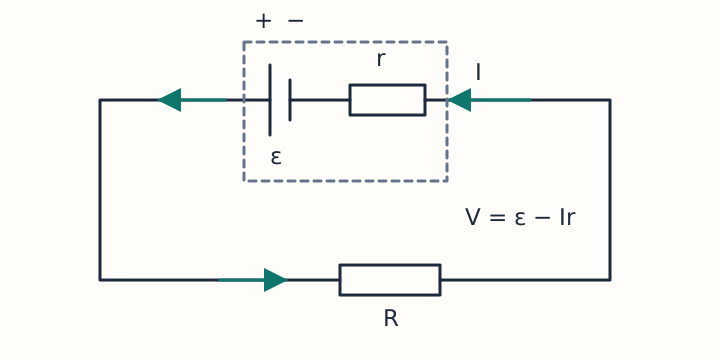
The current is limited by the external load resistance R and the internal resistance r of the source.
Terminal p.d. V is the energy per charge delivered to the external circuit. Ir is the “lost volts” inside the source.
Real-cell investigation
Predict how lowering the load resistance affects current, lost volts and terminal p.d. Then move one control.
Determining internal resistance experimentally
- Connect the cell, switch, ammeter and variable resistor in series; connect a voltmeter across the cell.
- Change the current and record paired terminal-p.d. and current readings. Open the switch between readings to reduce changes in cell temperature.
- Plot V against I. From V = ε − Ir, the vertical intercept is ε and the gradient is −r.
Part 3
Potential dividers and sensor circuits
The numerator is the resistance across which Vout is measured. A potentiometer provides a continuously variable output by moving the contact along a resistive track.
Sensor-divider designer
Choose whether the sensor is above or below the output. Predict the complete chain: stimulus → sensor resistance → output p.d.
Original exam-style practice
Analyse and justify
Q1. Resistors of 6.0 Ω and 3.0 Ω are in parallel. Find their total resistance.
1/R = 1/6.0 + 1/3.0 = 0.50 Ω−1, so R = 2.0 Ω. This is below the smallest branch resistance, as expected.
Q2. A 1.5 V cell with internal resistance 0.40 Ω supplies a 2.6 Ω load. Calculate current and terminal p.d.
I = ε/(R+r) = 1.5/3.0 = 0.50 A. V = IR = 0.50 × 2.6 = 1.30 V. The lost volts are Ir = 0.20 V.
Q3. A V-against-I graph has intercept 4.5 V and gradient −1.2 V A−1. State ε and r.
From V = ε − Ir: ε = 4.5 V and r = 1.2 Ω.
Q4. An LDR is the bottom resistor of a divider. Explain what happens to Vout as light intensity rises.
The LDR resistance decreases. Since Vout is measured across the LDR, its share of Vin decreases, so Vout decreases.
Q5. Two 1.5 V cells oppose one another in a loop. What is their net e.m.f.?
The sources act in opposite senses, so the net e.m.f. is 0 V. Always inspect polarity rather than automatically adding e.m.f.s.
Which statement must be true for two resistors in parallel?
A calculated divider output is 8.2 V from a 6.0 V supply. What should you do first?
OCR A specification coverage
Section 4.3 checklist
- 4.3.1(a) Apply Kirchhoff’s second law as conservation of energy in electrical circuits.
- 4.3.1(b) Apply Kirchhoff’s first and second laws to analyse electrical circuits.
- 4.3.1(c) Calculate total resistance of resistors in series using R = R₁ + R₂ + …
- 4.3.1(d) Calculate total resistance of resistors in parallel using 1/R = 1/R₁ + 1/R₂ + …
- 4.3.1(e) Analyse circuits with components including both series and parallel arrangements.
- 4.3.1(f) Analyse circuits with more than one source of e.m.f.
- 4.3.2(a) Define source of e.m.f. and internal resistance.
- 4.3.2(b) Define terminal potential difference and 'lost volts'.
- 4.3.2(c)(i) Use and apply E = I(R + r) and E = V + Ir for internal resistance.
- 4.3.2(c)(ii) Use techniques and procedures to determine the internal resistance of a cell or power supply.
- 4.3.3(a) Describe potential divider circuits with fixed components and potentiometers.
- 4.3.3(b) Describe potential divider circuits with variable components such as LDRs or thermistors.
- 4.3.3(c)(i) Use potential divider equations Vout = (R₂ / (R₁ + R₂)) × Vin and V₁ / V₂ = R₁ / R₂.
- 4.3.3(c)(ii) Use techniques and procedures to investigate potential divider circuits including sensors.
Mastery check
- Apply both Kirchhoff laws to unfamiliar circuits.
- Reduce series, parallel and mixed resistor networks.
- Handle several sources with correct polarity.
- Calculate and measure e.m.f., terminal p.d. and internal resistance.
- Design and explain fixed, variable and sensor potential dividers.
Complete the OCR electricity sequence
Revisit Charge and current or Energy, power and resistance. Return to the OCR Module 4 hub, use the OCR Paper 2 revision hub, or practise mixed calculations with PhysicsUK problem-solving questions.
Written against the current OCR A Physics A H556 specification. Question structures and misconception prompts are informed by official OCR assessment materials; all questions are original.